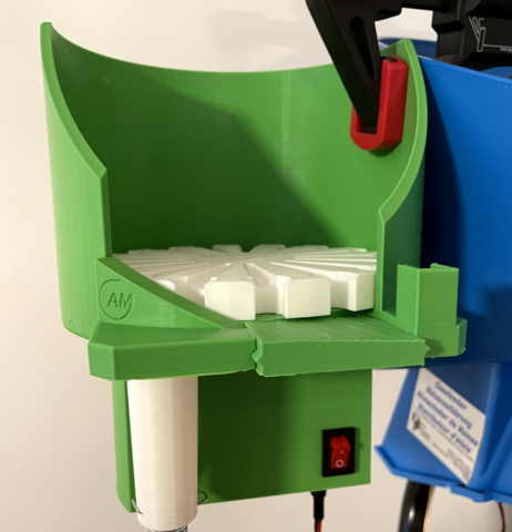
In reloading, especially when talking about pistol calibers, speed is everything.
If your shooting rate is high, automatization pays back really fast. But the initial investment sometimes is way too high.
Depends on the brand, but you can go from a single stage press and a set of dies for around 100-120€ total, to several thousands for a progressive press with full automation.
In this post I’ll share a 3D project for a bullet feeder I found online and what I used to make it fully functional.
Original 3D project with all corresponding files from “Ammo Mike” can be found in the vide description here.
Let’s talk first about the electronic part as the entire 3d model pack should be based on it:
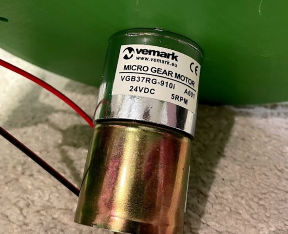
1. DC motor – if you can’t find the exact model mentioned in the info link, then you need to find a replacement and most important – you need to change the base stl file.
The perfect motor is around 4 to 8 rpm as per my observation. Faster will result failures or inconsistency, slower are fine, but they could be too slow if you have auto-drive for example.
Another thing to consider is the voltage – I chose 24V DC motor, 5rpm. The reason is simple – the original Dillon case feeder is also 24V with 1A power supply. So I got my motor with 2A power supply in addition and connected both case and bullet feeder with one power source.
2. On/Off switch, this is pretty straight forward, just get some you like. (optional)
3. Micro snap action switch – this is a tricky one, you need to get as light as possible, since the bullet is 7-8g, it should be able to “click” it. Also it could need a modification, by simply adding a longer lever if the original is too short. Note that you need a normally-closed (NC) option. So when the lever is not forced to click, the circuit should be closed.
4. Male + female DC connector pair (optonal)
5. Power supply – max current depends on the motor, I got 24DC 2A just in case and also because I used it to power the case feeder as well.
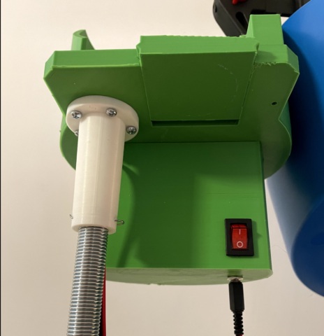
6. Spring – the one that connects the bullet collator with the die.
Also you’ll need a bullet dropper die. I used the Dillon one, but you can try whatever you have, also there are very nice 3d bullet feeder dies projects out there.
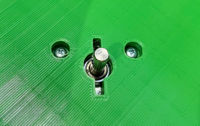
Once you got all you need, it’s time to modify the base stl file in order to mount your motor correctly.
I often see a requests in places like ThingiVerse for the original files. However, you can also directly edit the STL file without any problem and this is what I did, then my motor was mounted perfectly. You can find how from this Fusion 360 tutorial:
Once you have the base modified, it’s pretty straight forward process.
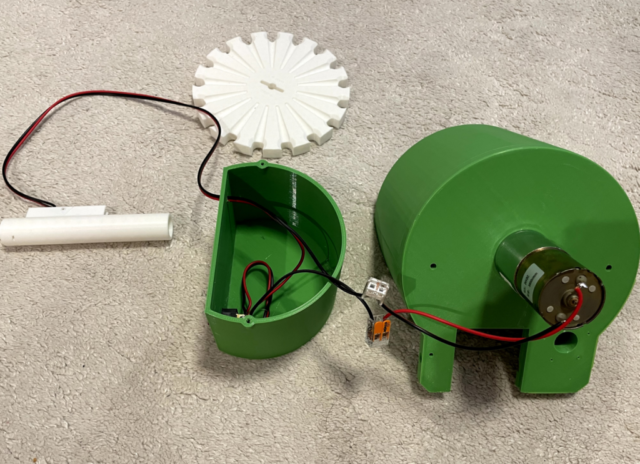
Just print out all needed parts.
Since there are some variations of the files (larger/smaller springs, different diameters etc), the author added a separate folder with the 9mm setup. However, I found that the included drop tube file was with too small diameter, so I printed out the 10mm one, which did the job: bf_v2_drop_tube_switch_small_id10mm_large_spring.stl
You can do this without the optional parts I mentioned above. However, it will look and feel much better if you add the On/Off switch + the DC connector.
Also you can see from the images that I made a motor cover, where I placed the optional parts as well. It really depends on what parts you’ll get as the model needs to be created based on them.
Here is a price breakdown for the entire project:
– DC Motor – 15€
– Power Supply – 12€
– Spring – 1.3€
– Micro switch, on/off button, dc connectors, a little wire – 4€
– PLA material 250-300g – around 7-8€
So in total it’s around 40€.
I must say it works perfectly and I already did ~1k rounds with the XL750.
I tested with both FMJ and Copper Plated 9mm bullets.
I’ll be happy to help if you have some questions about the models, wiring etc.
Currently I’m working on a case feeder project, which should be ready soon and I’ll put a separate post about it. Stay tuned. 🙂
